Why battery thermal management system design becomes a grid-level risk point
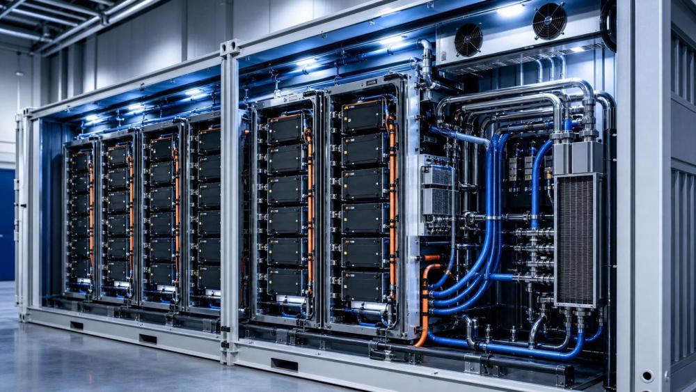
In large battery assets, heat control is tied to safety, dispatch stability, and usable project life.
That is why battery thermal management system design cannot be treated as a packaging detail.
A few degrees of imbalance may look minor in commissioning data.
In operation, the same deviation can amplify aging, trigger protection events, and weaken fire containment margins.
For ESGS-focused sectors, this risk spreads beyond the battery rack itself.
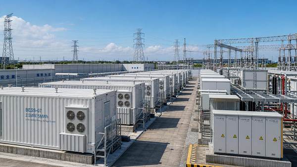
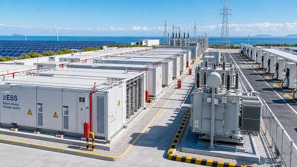
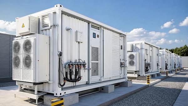
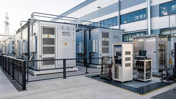
Grid-scale BESS containers, ultra-fast charging hubs, and hybrid energy platforms all depend on tight thermal discipline.
When thermal control drifts, the effect reaches PCS loading, availability, compliance evidence, and even revenue timing.
The practical question is not whether battery thermal management system design matters.
The real question is which failure risks appear first under different duty cycles and site conditions.
Actual operating conditions change the design priorities
Different applications ask the thermal system to solve different problems.
A four-hour BESS container is not judged the same way as a high-turnover charging station battery block.
One site may prioritize cell temperature uniformity over long discharge windows.
Another may need fast heat rejection during repeated peak-power events.
Ambient temperature also changes the failure map.
Desert projects face high external heat loads and dust fouling.
Coastal assets deal with corrosion, humidity, and sensor drift.
In colder regions, preheating logic and condensation control can become the weak link.
A sound battery thermal management system design therefore starts with duty profile, enclosure layout, and maintenance reality.
The first split is usually between energy throughput and power intensity
Long-duration storage accumulates heat over time and exposes uneven cooling paths.
High-power applications create sharper thermal spikes and stronger gradients near tabs, busbars, and interface plates.
That difference changes coolant strategy, sensor density, and control logic thresholds.
In BESS containers, the hidden risk is unevenness rather than average temperature
Grid-scale storage often appears thermally stable because average container temperature looks acceptable.
The harder issue is localized deviation across racks, shelves, and cell groups.
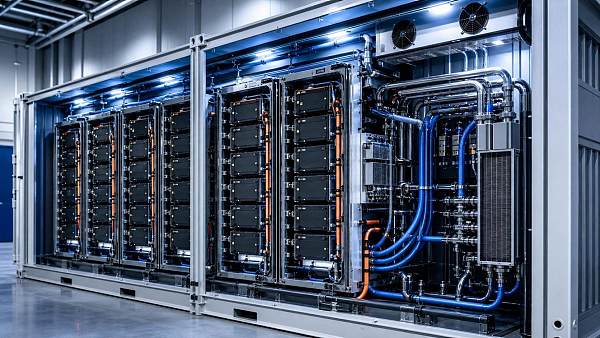
Battery thermal management system design for containerized BESS must keep delta-T under control during both charging and standby periods.
If airflow bypasses outer modules, or liquid paths are imbalanced, the hottest cells age faster.
That shifts internal resistance and makes later balancing less effective.
In practical operation, this often surfaces as capacity drift between strings before any obvious alarm appears.
For projects linked to renewable smoothing or peak shifting, this matters because dispatch models assume predictable available energy.
A thermal design flaw can therefore become a market participation problem, not only a safety problem.
What should be checked early in container projects
- Coolant path symmetry across parallel branches, not only nominal flow rate.
- Temperature sensor placement near likely hot spots, not only center locations.
- Control response during partial-load cycling, where thermal drift can stay hidden.
- Emergency operation after fan, pump, or valve degradation.
Fast charging and swapping sites expose a different set of thermal failures
At ultra-fast charging hubs, battery thermal management system design is pushed by power bursts, short rest periods, and dense equipment spacing.
The concern is less about slow cumulative heating across hours.
More often, the issue is repeated thermal shock and delayed cooldown.
This is common where liquid-cooled charging, buffer storage, and V2G functions share the same energy block.
A design that performs well in one full-power test may still struggle during rapid back-to-back sessions.
The failure sequence usually starts with hotspot persistence.
Then current derating appears, connector temperatures rise, and thermal reserves shrink for the next event.
In swapping environments, mechanical interface repeatability adds another variable.
Poor contact quality at thermal interfaces can create recurring module-level heat concentration.
The table shows why one battery thermal management system design rule cannot be copied across all high-power assets.
Failure risks often start in interfaces, controls, and maintenance limits
Many teams still focus on cell specification and cooling medium first.
In real projects, thermal failure often begins somewhere less visible.
One common issue is poor thermal contact between cells, plates, pads, and structural parts.
Another is control lag caused by sparse sensing or slow filtering logic.
A battery thermal management system design may look robust on paper, yet fail because alarms react to average values instead of fast local shifts.
Maintenance limits matter too.
If pumps, filters, valves, and heat exchangers cannot be serviced without long shutdowns, thermal performance will drift before anyone acts.
This matters for ESGS-tracked assets because uptime, compliance evidence, and long-term return are tightly linked.
Misjudgments seen repeatedly across projects
- Using nominal cooling capacity as the main acceptance metric.
- Assuming similar battery chemistries create identical thermal behavior.
- Ignoring dust, salinity, altitude, or enclosure pressure effects.
- Checking CAPEX closely while underestimating service access and replacement intervals.
- Treating UL 9540A or related safety testing as separate from daily thermal control strategy.
How to match battery thermal management system design to the site
A useful approach is to judge the design through three layers.
First, define the real thermal load profile, not only the nameplate load.
Second, test how the system behaves after one component degrades.
Third, check whether monitoring data is detailed enough to support action before protection trips.
For long-duration storage, prioritize uniformity mapping, flow balancing, and low-maintenance coolant management.
For charging and swapping assets, focus on transient response, cooldown recovery, and interface durability.
Where battery systems connect with digital twins, VPP dispatch, or frequency regulation controls, thermal data granularity becomes even more important.
A dispatch engine cannot optimize what the thermal system does not reveal.
Practical checks before final selection
- Compare maximum cell-to-cell deviation under real cycle simulations.
- Request degraded-mode performance after single pump or fan loss.
- Verify whether sensor points align with expected hotspot geometry.
- Review service intervals against actual shutdown tolerance.
- Link thermal thresholds with fire strategy, controls, and compliance records.
The next step is building a site-specific risk screen
The strongest battery thermal management system design is rarely the one with the most impressive brochure data.
It is the one that fits the duty cycle, environment, maintenance model, and safety path of the project.
Across BESS containers, charging hubs, and other high-power platforms, thermal failure usually develops through small mismatches that stay invisible too long.
A practical next move is to map operating scenarios, compare thermal limits against actual cycling behavior, and define acceptance criteria for degraded conditions.
That kind of review gives battery thermal management system design a clear role in reliability, compliance, and asset value instead of leaving it as a late engineering check.
Related News
 Battery Thermal Management System Design: Key Failure RisksGrid Storage ArchitectBattery thermal management system design shapes safety, uptime, and asset value. Explore key failure risks in BESS and fast-charging sites to improve reliability and performance.
 China Customs Adds New BESS Export Document ChecksGrid Storage ArchitectChina Customs adds new BESS export document checks for liquid-cooled BESS containers, raising 72-hour hold risks at Shanghai and Ningbo. Learn the new compliance files and how to avoid shipping delays.
 Choosing a Renewable Power Storage Solution for Wind Farm StabilityGrid Storage ArchitectRenewable power storage solution for wind farm projects: learn how to improve stability, cut curtailment, meet grid codes, and boost project value with the right storage strategy.
 Japan Tightens BESS Import Safety Label RulesGrid Storage ArchitectJapan Tightens BESS Import Safety Label Rules: learn how METI’s new UL 9540A and bilingual label requirements could delay Japan-bound BESS shipments, and what exporters should do now.
 BESS Safety Guidance for Utility Scale: What Actually Reduces Thermal Event RiskGrid Storage ArchitectBESS safety guidance for utility scale explained: discover which controls truly reduce thermal event risk, from propagation resistance to detection, isolation, and emergency planning.
 U.S. Customs Tightens BESS HTS ReviewGrid Storage ArchitectU.S. Customs tightens BESS HTS review with pre-clearance checks for liquid-cooled storage containers. Learn how 72-hour hold risks may impact delivery timelines, compliance, and U.S. project planning.
![]() Shenzhen Clearance Shift Pressures BESS Lead TimesGrid Storage ArchitectShenzhen clearance shift pressures BESS lead times as AI customs cuts dwell time from 32 to 9 days. See how BESS pricing, delivery planning, and EU-ASEAN battery trade may change.
Shenzhen Clearance Shift Pressures BESS Lead TimesGrid Storage ArchitectShenzhen clearance shift pressures BESS lead times as AI customs cuts dwell time from 32 to 9 days. See how BESS pricing, delivery planning, and EU-ASEAN battery trade may change. BESS Fire Safety Guidance: Key Design Risks to Check EarlyGrid Storage ArchitectBESS fire safety guidance starts early. Discover the key design risks in layout, cooling, venting, access, and test evidence before costly battery storage mistakes happen.
 EU Tightens Thermal Safety Rules for Liquid-cooled BESSGrid Storage ArchitectEU Tightens Thermal Safety Rules for Liquid-cooled BESS: learn how EN 50598-2:2026 affects EU market access, customs clearance, testing, and procurement before the October 2026 deadline.
 Battery Container Safety Systems: Top Failure Risks and FixesGrid Storage ArchitectEnergy storage safety systems for battery containers: uncover top failure risks, from thermal imbalance to detection gaps, and learn practical fixes to improve uptime, compliance, and grid reliability.
 Battery Cooling Systems for BESS: What Causes Thermal FailuresGrid Storage ArchitectBattery cooling systems for BESS: learn what causes thermal failures, spot early warning signs, and apply practical fixes to reduce risk, improve safety, and protect grid-scale storage performance.
 EU Tightens Thermal Runaway Tests for Liquid-Cooled BESSGrid Storage ArchitectEU tightens thermal runaway tests for liquid-cooled BESS under EN IEC 62933-5-2:2026. See how UL 9540A-aligned compliance affects CE marking, customs clearance, and EU market access.