Where energy storage systems integration usually starts to fail
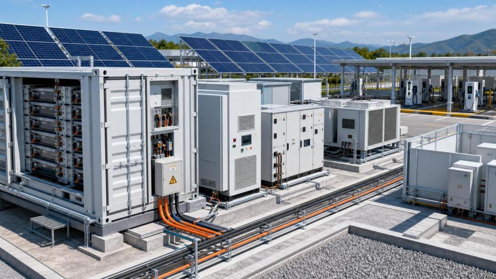
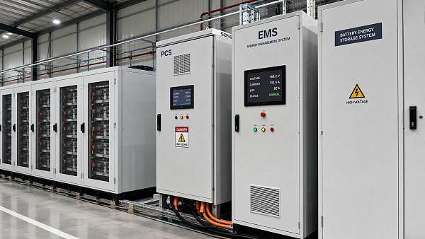
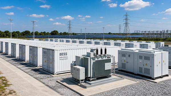
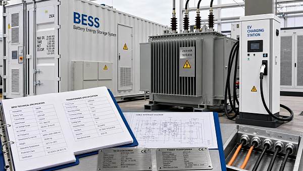
Energy storage systems integration looks straightforward on paper. Batteries, PCS, EMS, switchgear, HVAC, and protection systems appear modular. Site reality is rarely that clean.
When integration goes wrong, the issue is often not battery chemistry alone. It is the mismatch between electrical design, thermal control, software logic, grid code, and operating intent.
That is why energy storage systems integration affects both project bankability and day-two reliability. A plant can pass factory tests, yet still underperform once real dispatch patterns begin.
In practice, the most expensive failures appear at the boundaries. Container-to-PCS communication, EMS-to-grid response, fire strategy versus local code, or charging profiles versus ambient temperature often break alignment first.
For platforms like ESGS, which track BESS containers, UHV transmission, EV charging hubs, and hydrogen-linked power systems, this pattern appears repeatedly. Different assets share one problem: integration quality decides whether flexibility becomes revenue or risk.
The same storage architecture behaves differently across operating contexts
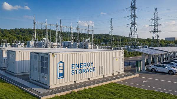
A four-hour BESS near a solar plant is judged differently from a fast-response system supporting frequency regulation. Both use energy storage systems integration, but dispatch stress, cycling depth, and fault tolerance differ sharply.
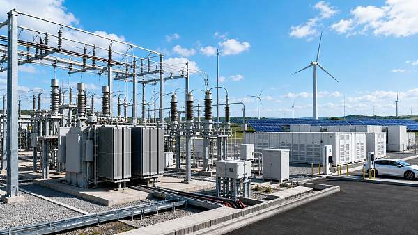
Grid-edge charging sites create another pattern. There, storage may buffer high-power chargers, manage transformer limits, and support V2G events. Millisecond control matters more than simple energy shifting.
In industrial microgrids, integration is judged by uptime and power quality. Harmonics, motor starts, islanding logic, and black-start sequence can matter more than headline capacity.
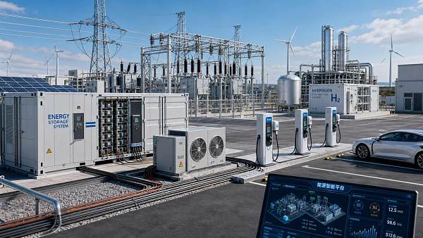
Hydrogen projects add yet another layer. If electrolyzers absorb curtailed power, the storage system must handle irregular ramps while coordinating with balance-of-plant controls. Here, energy storage systems integration is also process integration.
The better way to assess failure risk is to ask what the site is really trying to protect: arbitrage margin, grid stability, charging uptime, thermal safety, or process continuity.
A quick comparison of common operating priorities
At renewable-heavy sites, thermal and control assumptions break first
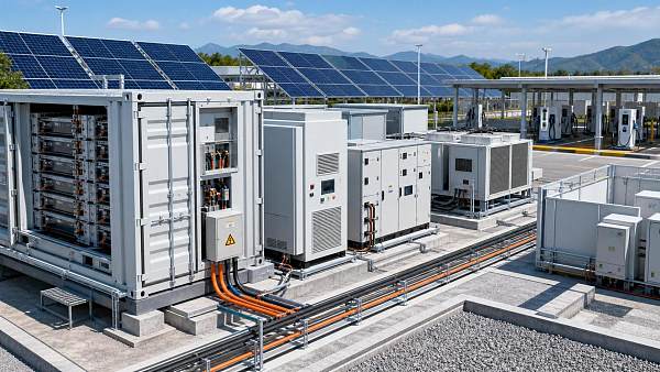
Co-located solar and storage projects often prioritize AC coupling simplicity or DC-side efficiency. The hidden risk is assuming average weather tells the whole story.
In hotter regions, containers may face repeated afternoon charge peaks exactly when cooling systems are already stressed. That is where energy storage systems integration can fail without any single component being defective.
A common fix is to simulate dispatch using real irradiance volatility, inverter clipping windows, and local ambient extremes. Liquid cooling setpoints, airflow routing, and charge-rate limits should then be tuned together.
Another frequent mistake is using generic degradation curves. Projects tied to merchant markets or capacity contracts need integration settings that protect availability during revenue-critical hours, not only annual energy throughput.
Fast-response grid support exposes software timing problems
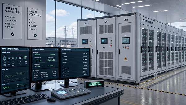
Frequency regulation and synthetic inertia applications reward speed, but speed amplifies software weakness. A delay of a few hundred milliseconds can erase expected value or trigger compliance concerns.
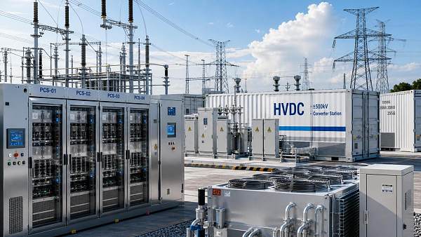
Here, energy storage systems integration depends on clean signal flow across EMS, SCADA, PCS, and protection relays. Data tags, timestamp quality, and fallback modes are not administrative details. They are operating assets.
More than one project has passed FAT and SAT while still failing field performance because command priority was unclear. Local controls tried to protect battery health while market controls chased response speed.
The practical remedy is staged commissioning. Test autonomous mode, remote dispatch mode, and degraded communications mode separately. Then verify what happens when they overlap under grid disturbance.
Charging hubs and swapping stations create a different integration logic
At mega charging sites, storage is usually installed to avoid transformer upgrades, reduce demand charges, or smooth ultra-fast charging peaks. Those goals can conflict during busy traffic windows.
If charger management software treats storage as unlimited buffer power, battery stress rises quickly. If the storage EMS becomes too conservative, queue times increase and the site loses commercial value.
This is where energy storage systems integration should be judged by command hierarchy. Which system wins when charger demand, grid import cap, and battery protection disagree?
Sites planning future V2G capability need another layer of caution. Bidirectional flows can change harmonics, metering logic, and interconnection assumptions. Integration should be designed for that future state, not patched later.
ESGS closely follows these charging-storage interactions because they connect mobile loads, distributed storage, and grid flexibility into one control problem rather than three separate products.
Industrial microgrids and hydrogen coupling fail in less obvious ways
Microgrids are often treated as smaller utility projects. That is misleading. Site loads may include crushers, pumps, furnaces, or process lines with abrupt transients and strict uptime constraints.
In these settings, energy storage systems integration must align with motor starting sequences, breaker coordination, and islanding transitions. A battery that looks oversized on paper can still trip on a poorly timed transfer event.
Hydrogen-linked projects introduce dispatch irregularity from the other direction. Electrolyzers can act as flexible loads, but only within process limits, water quality constraints, and balance-of-plant response times.
The integration lesson is simple. Do not model storage and electrolysis as independent blocks. Treat them as one coordinated flexibility system with electrical, thermal, and process boundaries.
Misjudgments that keep repeating across projects
Most recurring problems are not exotic. They come from reasonable assumptions applied in the wrong context.
- Selecting by nameplate power and energy, while ignoring local dispatch volatility and seasonal heat.
- Using one-line diagrams that omit communications latency, control ownership, and fail-safe behavior.
- Checking capex carefully, but underestimating commissioning time, firmware alignment, and spare parts strategy.
- Treating similar sites as identical, even when grid code, transformer headroom, or fire rules differ.
- Planning around initial operation only, without considering later expansion, VPP participation, or hybridization.
A stronger approach is to use site-specific integration reviews. ESGS often frames this through three lenses: safety boundaries, dispatch logic, and lifecycle economics. That combination usually reveals hidden conflicts early.
What to confirm before commissioning and scale-up
Before energization, confirm that energy storage systems integration has been tested beyond component compliance. The full operating chain matters more than isolated certificates.
- Map all control layers, including local overrides, utility signals, and emergency shutdown logic.
- Validate thermal behavior under worst dispatch days, not average performance days.
- Review protection coordination against actual site faults, charger peaks, or process load transients.
- Check that fire strategy, UL 9540A assumptions, and local code interpretations are aligned.
- Recalculate LCOS using expected degradation, auxiliary consumption, and curtailment reality.
For expansion phases, it is worth establishing a repeatable integration standard. That should include communications templates, protection philosophy, thermal design margins, and a digital record of commissioning logic.
Energy storage systems integration delivers its best value when the site model reflects actual operating pressure. The next step is usually clear: define the real scenario, compare the constraints, and test the interfaces before revenue depends on them.
Related News
 Energy Storage Systems Integration: Common Failures and FixesGrid Storage ArchitectEnergy storage systems integration often fails at control, thermal, and commissioning interfaces. Discover common faults, practical fixes, and how to improve BESS reliability and project ROI.
 IEC 62933-5-2:2026 Sets VPP Interface Rules for PCS and EMSGrid Storage ArchitectIEC 62933-5-2:2026 sets new VPP interface rules for PCS and EMS, requiring IEEE 1547.4a-2026 parsing and millisecond response. Learn how this may impact exports, tenders, firmware planning, and compliance.
 C&I Storage Tenders Jump 47% as PCS and EMS Gain WeightGrid Storage ArchitectC&I storage tenders jump 47% as PCS and EMS gain weight, signaling a shift toward AGC response, VPP compatibility, and compliance. See what buyers now value most.
 Energy Intelligence Platforms: Which Data Features Matter Most in Daily Operations?Grid Storage ArchitectEnergy intelligence platforms work best when real-time, decision-grade data drives safer dispatch, faster fault response, and stronger asset returns across storage, grids, EV charging, and hydrogen.
 PCS Selection Power Rating: How to Size for Peak Load and Battery ThroughputGrid Storage ArchitectPCS selection power rating explained: learn how to size PCS for peak load, battery throughput, thermal limits, and grid performance to improve BESS uptime, revenue, and project value.
 Smart Grid Equipment in North America: Cost and Upgrade PrioritiesGrid Storage ArchitectSmart grid equipment North America buying guide: compare cost, resilience, and upgrade priorities across substations, automation, AMI, and renewables to make smarter utility investment decisions.
![]() Power Conversion System Manufacturer Checklist for Reliable BESS IntegrationGrid Storage ArchitectPower conversion system manufacturer checklist for reliable BESS integration. Compare compliance, performance, thermal control, lifecycle cost, and service strength to shortlist lower-risk suppliers.
Power Conversion System Manufacturer Checklist for Reliable BESS IntegrationGrid Storage ArchitectPower conversion system manufacturer checklist for reliable BESS integration. Compare compliance, performance, thermal control, lifecycle cost, and service strength to shortlist lower-risk suppliers.![]() EU Revises CE Guidance for VPP-Linked PCS and EMSGrid Storage ArchitectEU revises CE guidance for VPP-linked PCS and EMS, making EN 50549-3:2026 testing critical. See how exporters can avoid customs risk, delays, and lost EU deliveries.
EU Revises CE Guidance for VPP-Linked PCS and EMSGrid Storage ArchitectEU revises CE guidance for VPP-linked PCS and EMS, making EN 50549-3:2026 testing critical. See how exporters can avoid customs risk, delays, and lost EU deliveries. Power Conversion Systems Manufacturer Checklist for Grid-Scale ProjectsGrid Storage ArchitectPower conversion systems manufacturer checklist for grid-scale projects: compare compliance, thermal design, integration, safety, and service to reduce risk and improve long-term returns.
 How Power Flow Control Systems Hardware Improves Grid StabilityGrid Storage ArchitectPower flow control systems hardware improves grid stability with faster fault response, voltage control, and renewable balancing. See how it supports BESS, EV charging, HVDC, and resilient power networks.
 How to Use an Energy Equipment Specification Format Without Missing Critical DataGrid Storage ArchitectEnergy equipment specification format guide: learn how to capture critical technical, compliance, and lifecycle data, reduce vendor gaps, and improve project delivery with a practical checklist.
 How Power Flow Algorithms for Grids Improve Stability and Dispatch AccuracyGrid Storage ArchitectPower flow algorithms for grids improve stability, congestion visibility, and dispatch accuracy across BESS, UHV, EV, and hydrogen networks—see how smarter modeling boosts grid decisions.